Appendix E–LNAPL Sheens Appendix
1.0 Introduction–What Are LNAPL Sheens?
Petroleum sheens (Figure S-1) can be encountered in surface water near facilities where historical subsurface petroleum releases have occurred. The occurrence of petroleum sheens may result in notices of violation and fines issued by regulatory agencies, as well as undesired publicity and aesthetic issues. In some cases, a rapid response is necessary.
Typical remedies for petroleum sheens in surface water may include adsorbent booms, physical barriers, hydraulic controls, or excavation of impacted soils. Though successful in some cases where deployed, these remedies may be less effective than desired, can conflict with other facility goals, and/or may have high cost of implementation.
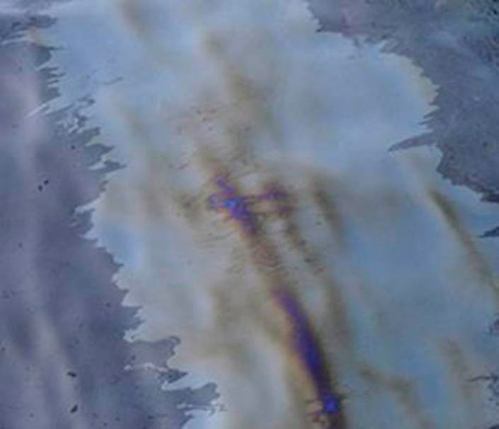
Figure S-1. Petroleum sheen on surface water (Sale and Lyverse 2014).
Governing Processes
Effective management of sheens begins with an understanding of governing processes.
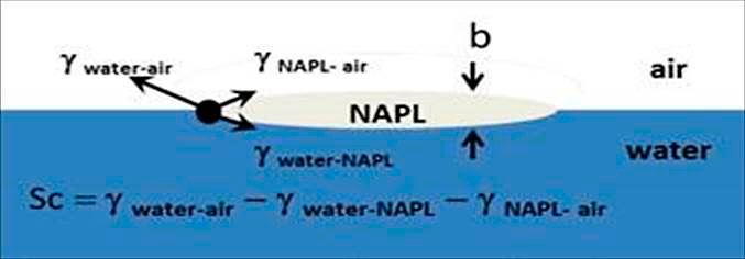
Figure S-2. Forces controlling spreading of LNAPL across air-water interfaces ([popuppress id=”51627″]).
Spreading–Petroleum sheens occur when petroleum liquids (referred to as Non-aqueous Phase Liquids–NAPLs) spread across air-water interfaces. The potential for a NAPL to spread is defined by the spreading coefficient (Sc). This concept is presented in Figure S-2. NAPLs spread across air-water interfaces until interfacial forces (γ) at the leading edge of the sheen are balanced or natural processes (e.g., dissolution and volatilization) deplete the petroleum liquids. Most petroleum NAPLs (crude oil, fuels, and lubricants) will spread across surface water as described above. Spreading may be enhanced by biosurfactants that are associated with biological degradation of NAPLs in subsurface media including sediments, soils, and rock.
Characteristics
Thin films–Sheens are so thin that the equivalent amount of petroleum liquids can be as low as a few liters per square kilometer (ten liters per square kilometer equates to a thickness of 0.00001 mm).
Appearanc –The iridescent color of sheens is due to refraction of light through thin NAPL layers with varied thicknesses.
Origin–Sheens are commonly associated with releases of petroleum liquids near surface water bodies. They can also be due to biological degradation of naturally occurring organics (i.e., plant material). Natural sheens can occur in stagnant water associated with organic rich sediments (e.g., swamps).
Natural Losses–Hydrocarbons associated with petroleum are subject to a diverse set of natural loss processes. In the case of sheens on surface water, natural loss processes include volatilization, microbially mediated aerobic degradation, and dissolution into water. In sediments and groundwater systems, microbially mediated anaerobic processes can also play an important role in mitigating impacts associated with petroleum at groundwater-surface water interfaces. Depending on the composition of released petroleum and environmental conditions, sheens can persist for minutes to days. Critically, natural losses prevent sheens from being more common. Enhancing natural losses of petroleum hydrocarbons at groundwater-surface water interfaces (GSIs) is an emerging strategy for managing sheens.
Sheen Occurrence–Sheen occurrence can correspond to low surface water stage, high surface water stage, seasonal temperatures (Chalfant 2015) or ebullition (McLinn and Stolzenburg 2009). Understanding processes controlling sheens at individual sites can be difficult. With study, mechanisms governing the cause of a sheen can usually be resolved. In general, sheen appearance is dependent on a) the mechanism of releases and b) seasonally varying factors controlling natural losses of NAPLs at groundwater-surface water interfaces.
2.0 What are Some Important Regulatory Requirements Concerning Sheens?
According to Clean Water Act, 40 CFR, Chapter I, Subchapter D, Part 110, Section 110.1, a sheen is defined as “an iridescent appearance on the surface of water”. https://www.epa.gov/sites/production/files/2014-04/documents/b_40cfr110.pdf
Part 110.3 discusses the types of discharge of oil that the EPA Administrator has determined may be harmful to the public health or welfare or the environment. One is a discharge oil that may “cause a film or sheen upon or discoloration of the surface of the water or adjoining shorelines.” Section 110.6 states that any person in charge of a facility, as soon as he or she has knowledge of a sheen that is in violation, shall immediately notify the National Response Center (NRC) at 800-424-8802. The NRC will relay the information to the On-Scene Coordinator (OSC) of the US EPA or U.S. Coast Guard, depending on the location. After receiving the report, the OSC will determine if federal emergency response action is necessary.
https://www.epa.gov/sites/production/files/2014-06/documents/spccfactsheetspillreportingdec06-1.pdf
If direct reporting to the NRC is not practical, reports may be made directly to the Coast Guard or a designated EPA OSC in the geographic area where the discharge occurs.
In addition to reporting to the NRC, some states also have separate reporting requirements for sheens. For example, some states have reporting requirements for spills or discharges directly into state waters if the quantity is sufficient to create a sheen (example: Texas). Other states have reporting requirements for sheens in navigable waters (example: Ohio). In addition, depending on the state, the responsible person may be required to: immediately abate and contain the spill or discharge that caused the sheen, cooperate fully with local and state authorities, and submit various documentation to state authorities. If a sheen occurs, the responsible party should check with state authorities to determine what additional requirements may be necessary.
3.0 What Are the Common Sheen Forming Scenarios and Processes?
Understanding mechanisms of releases and factors controlling natural losses of NAPL is central to developing remedies. As described below, it is not unusual for the occurrence of sheens to be episodic and related to hydrologic, atmospheric (i.e., changes in barometric pressure) or water stage/level conditions as described below. At any site, one or more of these mechanisms might be at play.
Scenarios
Seeps–Groundwater typically discharges from river banks or shorelines to surface water during falling surface water levels. Given NAPL near the GSIs, discharge of groundwater can drive NAPL sheen into surface water (Figure S-3). Most often, NAPL seeps appear at low surface water stages. As shown in Figure S-3, seeps are generally oriented parallel to the shoreline.
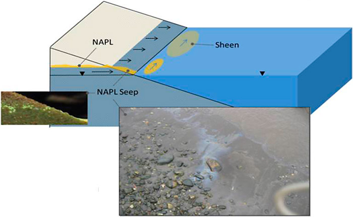
Figure S-3. Sheen from NAPL seep (Drawings by Sale and Lyverse 2014).
Ebullition–The term “ebullition” (Conger 1943); (Amos et al. 2005) has been used to describe the process of gas generation and discharge from sediments. Biodegradation of naturally-occurring organic compounds or of the petroleum itself that is affecting sediments, can generate gases that migrate upward through sediments due to buoyancy. NAPLs are hydrophobic and preferentially attach to the surface of a gas bubble passing through, which subsequently transports the NAPL to the air-water interface. NAPL-coated bubbles reaching the surface of a water body yield a sheen because the surface tension of water is much higher than petroleum. This process was described by (McLinn and Stolzenburg 2009).
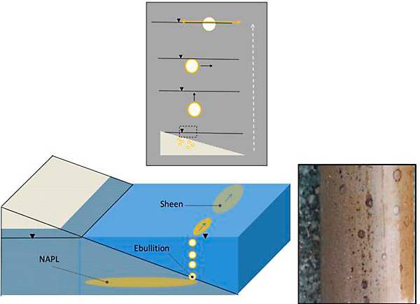
Figure S-4. Sheen from ebullition (Drawings by Sale and Lyverse 2014).
(Photograph provided by Dr. Julio Zimbron, authorization to use by Author/Colorado State University)
Sheens created from ebullition are episodic. The processes that trigger the coalescing of gas bubbles that move out of sediments and migrate upward to the surface of a water body are an area of current research. Conceptual models for conditions that can trigger ebullition include rising, water levels, falling water levels, temperature changes, and certain tidal conditions. Figure S-4 illustrates sheens generated from ebullition process. The lower right photo in Figure S-4 shows gas bubble formation within a core sample.
Erosion–Another mechanism driving sheens is erosion of sediments and soils. Erosion can occur at high flows along rivers, due to storm-related wave actions, construction activities, and/or ice scour. Soils containing residual LNAPL are now placed in direct contact with the air/water interface at the sediment surface (Figure S-5).
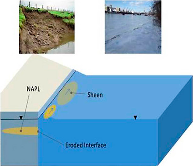
Figure S-5. Sheen from shore or bank erosion (Drawings by Sale and Lyverse 2014).
Animations of the scenarios described above can be found here. (courtesy of ACRADIS USA.)
Processes
Process-based insights developed from laboratory studies are described in the following text.
Sheens in Porous Media–NAPLs can move across the air-water interface in porous media (at the top of the capillary fringe) in a manner similar to the spreading of sheens on surface water (Figure S-6). Initial spreading rates as high as meters per minute were observed. With time, rates of spreading slowed as the NAPL was attenuated by dissolution. Visual observations suggest that sheen releases at the GSI can occur due to NAPL spreading along air-water interfaces in porous media as shown in Figure S-6.
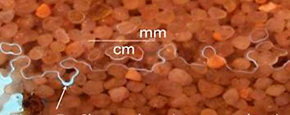
Figure S-6. Sheen advancing across the air-water interface at the top of the capillary fringe.
(Provided by Dr. Julio Zimbron, authorization to use by Author/Colorado State University.)
Ebullition–As previously introduced, where gases are generated in sediments adjacent to NAPLs, rising gas bubbles can carry coatings of NAPL (much like an outer coating on chocolate candy) to the water surface, forming sheens (Figure S-4). Laboratory studies and field observations provide the basis for the prior discussion of ebullition-based release mechanism for sheens. Ebullition associated with NAPLs has been discussed in various papers including [(Amos et al. 2005); (Yuan et al. 2007); (Yuan, Valsaraj, and Reible 2009); (McLinn and Stolzenburg 2009); (Viana et al. 2007).
Water Level Fluctuation–In most cases, the mobility of NAPL in a geologic formation depends upon water level stage in the media. At high water levels, NAPL in porous media is occluded by the rising water and can be present as discontinuous ganglia and blobs of NAPL that are effectively immobile. Correspondingly, at low water stages, some of the NAPL can be mobile as either a continuous non-wetting phase in the saturated zone or as an intermediate wetting phase in the unsaturated zone. The capacity of the porous media to release NAPL is (generally) much greater at low water stages. Common factors controlling water levels at groundwater-surface water interfaces include tides, seasonal variation in stream flows, local groundwater extraction, and extreme weather.
4.0 What Are Methods to Identify Petroleum Derived Sheens?
Sheen Observation
As part of periodic monitoring, the locations of visually identified sheens should be recorded on field maps, photographed or observed with and without polarizing filters, and physical characteristics of the sheens recorded in a field form. While visual observations of sheens cannot be used to definitively determine sheen composition, important properties and characteristics of sheens can be visually assessed. Sheens observed during monitoring can be characterized based on visually observable physical properties:
- approximate size/dimensions of the sheen
- percentage of the water surface with visible sheen in the general area containing the sheen
- color of the sheen
- sheen structure (no structure, angular, patch, streamers, windrows, oil spots)
- orientation of sheen streamers, if present
- sheen blossom frequency, if applicable
- sheen brittleness based on how the sheen responds when disturbed (Figure S-7)
- Brittle: sheen that cracks, breaks apart, or disaggregates upon disturbance. Brittle sheens are often of natural biogenic origin indicating that the sheens may be associated with microbial activity.
- Non-brittle: sheen that rapidly coalesces upon disturbance. Non-brittle sheens are often related to anthropogenic sources, including petrogenic sources (e.g., petroleum hydrocarbons such as crude oil, gasoline, diesel fuel, and asphalt) and pyrogenic sources (e.g., combustion-related materials such as coal tar and creosote). Sheens can also be derived from petrogenic source materials that have been subjected to pyrogenic processes, such as used motor or used hydraulic oil.
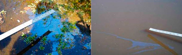
Figure S-7. Brittle sheen (left) and non-brittle sheen (right) (Stout and Uhler 2016).
In addition, surface water flow conditions and actions taken to remove the sheens should be noted.
The National Oceanographic and Atmospheric Administration (NOAA) published a document to assist responders in describing and characterizing oil spills on open water (NOAA 2016), and for consistency observed sheens should be characterized using NOAA specified terminology (e.g., color, structure).
When observing and photographing sheens, a polarizing filter can be used to provide a line of evidence regarding the source of the sheen. When rotating the polarizing filter through 180°, the sheen appearance will change. Biogenic sheens may appear blue to bluish purple at one orientation of the polarizing filter.
Sheen Sampling
In addition to periodic sheen monitoring activities, sheen sampling may be conducted. Sheen samples may be collected using an oil spill net sampler with a highly porous TFE-fluorocarbon polymer net attached to a disposable ring. The net is passed through the surface sheen to collect the sample. The net is then removed from the disposable ring and placed into a 4-ounce glass sample jar with a Teflon®-lined cap. Samples are placed into a cooler and shipped under appropriate chain of custody procedures to the analytical laboratory.
The objectives of the sheen sampling are to:
- Compare the composition of the sheen to known LNAPL release material.
- Assess potential additional sources of sheens based on chemical characteristics.
- Evaluate the possible relationship between sheen chemical properties and observed physical characteristics.
Sheen sampling should include the collection of sheens identified during monitoring as both as brittle and non-brittle. Sheen sampling locations should be identified on the field form.
In addition to the above sheen sampling activities, it is suggested that a sheen net blank and a laboratory generated sheen sample be analyzed. The analysis of a sheen net blank is conducted to determine whether sheen samples are affected by constituents derived from sheen net material. Analysis of a sheen generated under controlled (laboratory) conditions using suspected source material is conducted for comparison and potential identification of sheen samples.
To facilitate correlation of sheens to their sources, it is recommended that sheen samples, a sheen net blank sample, and a laboratory-generated sheen sample be analyzed for the following parameters:
- polycyclic aromatic hydrocarbons (PAHs) and biomarkers by USEPA Modified Method 8270 Select Ion Monitoring
- aliphatic and total petroleum hydrocarbons (TPH) by USEPA Modified Method 8015
Interpretation of Sheen Sample Results
Petroleum hydrocarbon forensics, or “fingerprinting,” is an important tool used to evaluate the chemical composition and source of sheens. Analytical results can then be used to identify the type(s) of petroleum hydrocarbons present, assess potential source(s), and evaluate the extent of weathering of petroleum hydrocarbons at environmental sites.
Petroleum hydrocarbon products, including gasoline, diesel fuel, motor oil, and crude oil, are complex mixtures consisting of 100s to 1,000s of different compounds. The chemical composition of petroleum hydrocarbon products varies due to several factors including crude oil source, subsequent refining processes, and weathering processes (e.g., volatilization, dissolution, and biodegradation). Because of the complex composition of petroleum hydrocarbons, numerous analytical “forensic” techniques have been developed to characterize petroleum hydrocarbons based on the molecular mass and structure of compounds.
As part of a petroleum hydrocarbon forensic assessment, analytical results from samples are compared to analytical results and chromatograms for known or suspected sources. Analytical results from sheen samples can be compared with the analytical results from a sample of suspected source material, a laboratory generated sheen, a sheen net blank, and literature values for other potential sources of sheens or hydrocarbon constituents. Table S-1 summarizes the sources of PAHs in the environment.
Table S-1. Potential sources of PAHs in the environment
| Petroleum Products | Combustion Products | Coal Derived | Plant Derived |
|---|---|---|---|
| Crude Oil Kerosene Jet Fuel Diesel Fuel Heating Oil Engine Oil Used Engine Oil Used Hydraulic Oil Asphalt |
Coal Tar Creosote Petroleum-Derived Soot Forest Fire Ash Used Engine Oil Used Hydraulic Oil Asphalt |
Coal Tar Creosote Coal Coal Ash Coal-Derived Soot |
Peat Lignins Pine Forest Fire Ash |
| Sample comparisons are based primarily on direct comparison of chromatograms generated from the laboratory analysis of samples as well as bar charts generated from the distributions of detected concentrations of PAH and aliphatic petroleum hydrocarbon compounds. Figure S-8 illustrates an example where chromatograms and plots of PAH and biomarker ratios were used to confirm the source of a sheen-forming seep. | |||
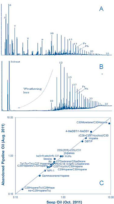
Figure S-8. Tier 1 GC/FID chromatograms of (A) 2011 pipeline oil and (B) 2011 mystery oil seep. (C) shows a high correlation (r2=0.99) between 18 of these oils’ diagnostic ratios based on PAHs and biomarkers. These oils “match.” Numbers in (A) and (B) refer to n-alkane carbon numbers, Pr-pristane, Ph-phytane (Hawkins 2012).
Additional information on petroleum analyses and petroleum forensic chemistry is available in ITRC TPH-Risk (ITRC 2018).
5.0 What Tools are Available to Assess Flux from Seeps?
The measurement of seep fluxes and sheen occurrence is complicated by their episodic nature, which makes observation challenging. Technological solutions including remote monitoring may improve this process in the near future. Table S-2 summarizes some manual techniques for measuring seep mass flux.
Table S-2. Methods for assessing seep flux
| Method | Example | Description |
|---|---|---|
| Direct Methods | Visual Observation / Surveillance
|
Direct aerial observation. (NOAA 2016) tools can also be used to classify sheens observed from land. Video surveillance can be used in areas prone to sheening due to ebullition. |
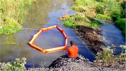
| Corral Sampler
|
A “corral” sampler, to quantify sheen generation. (Stolzenburg, Rice, and Vater 2012) | |
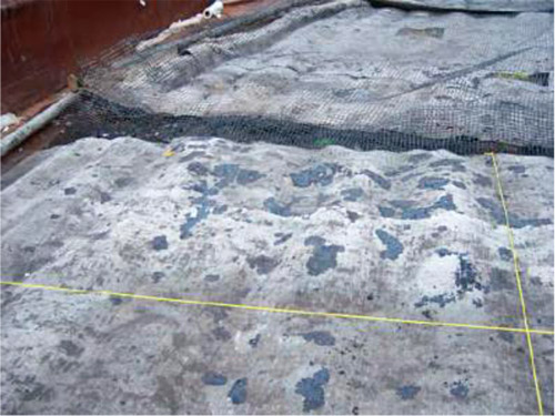
| Sorbents
|
Cover area susceptible to seeps. Collect and measure mass of hydrocarbons collected. Reactive Core Mats (RCM) are deployed on the bed of the water body. Sorbent pads and sheen nets are used on the surface of the water body. (EPRI 2011) | |
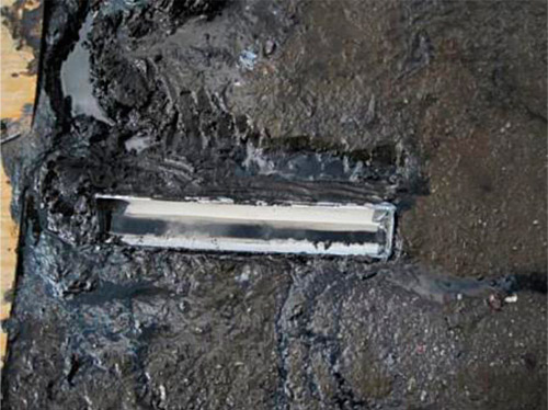
| Collection Trench
|
An impermeable collection device (e.g., 4″ PVC pipe cut in half) of known dimensions will be placed in the trench, so that the lip of the collection pipe is flush with the mudflat and the pipe intercepts the water/LNAPL seeps flow. Observations will be made at regular intervals, depending on collection rate, to observe the accumulation of water/LNAPL within the pipe. | |
Submerged Gas Collection Devices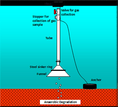 |
Devices deployed underwater to collect gas bubbles for the estimation of ebullition mass flux. (Viana et al. 2007) | |
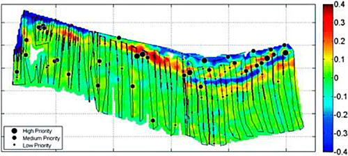
| Indirect Methods | Distributed Temperature Sensing
|
Temperature sensing fiber optic cables deployed on a sediment bed. Detects thermal anomalies that are attributed to seep zones. (Selker et al. 2014) |
6.0 Potential Sheen Mitigation Technologies
Remedy selection for sheen mitigation is a complex process that is dependent on site-specific factors. During site characterization and conceptual site model development, the potential source(s) of LNAPL causing sheens should be identified, particularly considering the dynamic nature of coastal or river environments, and multiple potential sources of oil or sheens given this setting. This is important to avoid potentially costly remedies to address sources not associated with the upland site. Certain remedies, if located in the wrong area (for example, in an upland area when source contamination is in the foreshore), will not be effective.
With a good LNAPL site conceptual model (LCSM) in hand, a site-specific remedial objective can be developed, and technologies described below in Table S-3 are options for consideration. As in the case of upland LNAPL remediation, more than one sheen mitigation technology may be used in a given situation.
Table S-3. Sheen remedies
| Remedy | Primary Niche | Technology Status | Potential Advantages | Potential Limitations |
|---|---|---|---|---|
| Adsorbent Booms | Early response | Proven–well understood |
|
|
| Sheet Pile Wall | Large-scale subsurface releases | Proven–well understood |
|
|
| Subsurface Hydraulic Recovery of LNAPL | Sites with limited access to GSIs | Proven–well understood |
|
|
| Organoclay Barriers | Sites with depleted NAPL sources | Proven–Multiple sites |
|
|
| Sediment Caps | Sites with on-going NAPL releases | Proven–Full-scale caps in place |
|
|
| Capillary Barriers | Sites with depleted NAPL sources | Innovative–a few well studied field applications |
|
|
| Oleophilic Bio-Barriers | Sites with depleted NAPL sources | Emerging–one well-studied field application |
|
|
In this document, sheen mitigation technologies are divided into three categories: Temporary, Conventional and Emerging. The technologies discussed here are limited to the mitigation of sheens. Oil spill recovery involves additional technologies and techniques that are beyond the scope of this document. Readers should refer to references by the US Coast Guard, NOAA, and the Marine Oil Spill Response Corporation.
Historically, the conventional sheen mitigation technologies described below have proven to be effective. However, associated costs for capital and operations and maintenance (O&M) have been large.
Decision makers and stakeholders should be aware of factors that can lead to failure of mitigation technologies over extended time periods. Factors leading to failure include incomplete characterization of affected soils/sediments, LNAPL bypass around or through remedy components, finite life-times of remedy components, and/or excessive LNAPL loading. Hopefully, emerging technologies will provide more sustainable and resilient solutions to mitigate low-mass-flux sheens. Such technologies, when they also incorporate biodegradation processes, are potentially more sustainable than conventional approaches based on physical controls.
Booms–Constructed of absorbent material, booms are devices deployed to the surface of waterways to divert, deflect or contain sheens or serve as a preventive measure for intermittent sheens (NOAA 1994). Relative to other technologies, booms are less rugged over the long term and must be carefully maintained. Due to inhalation and flammability hazards, booms are generally not used to contain gasoline (NOAA 1994). Oil skimmers can be deployed within boomed areas when sufficient amounts of oil are present.
Subsurface Hydraulic Recovery–Adjacent to shorelines, hydraulic LNAPL control can be deployed to abate LNAPL movement. The technology attempts to reverse the LNAPL hydraulic gradient away from the water body and reduce LNAPL saturation levels towards residual saturation. The effectiveness of this technology depends upon the quality of the LCSM and a sound system design that ensures capture.
Barriers/Berms–Intended to be more permanent structures to control or divert sheens. Sheet pile walls are a common engineered physical barrier. Life-cycle planning is a consideration for physical barriers because they can alter the hydraulics of the water body and are not easily removed once installed. Further, although relatively resilient, there is a finite lifespan to sheet pile barriers. Other types of barriers include trenches that can collect LNAPL for recovery, or bubble barriers that can promote volatilization and biodegradation (NOAA 1994).
Organoclay Barriers–Organoclay is an expansive clay in which charged organic compounds (organic amines) are introduced between the silicate sheets (layers) in the clay. Organic compounds make the clay surfaces oleophilic (oil-loving). Either pure organoclay, mixtures of organoclay and sand, or organoclay in a geotextile mat have been placed at GSIs.
Sediment Caps–Sediment caps that reliably and effectively trap and sequester ongoing LNAPL or DNAPL releases from sediments have been described (Rice et al. 2013), and designed and constructed at several locations. The design features of these caps can incorporate the Oleophilic Bio Barrier (OBB) technology (see below) and/or reactive treatment material for addressing the accumulating NAPL. Long-term effectiveness and adaptability to a wide variety of site conditions are two significant advantages of these caps.
Emerging–Two promising technologies for managing sheens are described in the following section. One has been studied in laboratory experiments (Capillary Barriers), the second has been piloted (Oleophilic Bio Barriers).
Capillary Barriers–Unpublished research conducted by Dr. Tissa Illangasekare, Colorado School of Mines and G.D. Beckett, AquiVer Inc. indicates that vertical walls of well-sorted fine-grained sand can preclude lateral movement of NAPL while allowing water to pass. Given water as the wetting fluid and NAPL as the non-wetting fluid, pressure in the NAPL relative to pressure in the water (a function of NAPL head, density and interfacial tension) needs to be great enough to exceed the displacement pressure of the water in the porous media. Given these conditions, the application of capillary barriers would most commonly be under conditions of sub-horizontal groundwater and/or NAPL movement. Capillary barriers should also be designed to address potential ebullition of gases, if occurring.
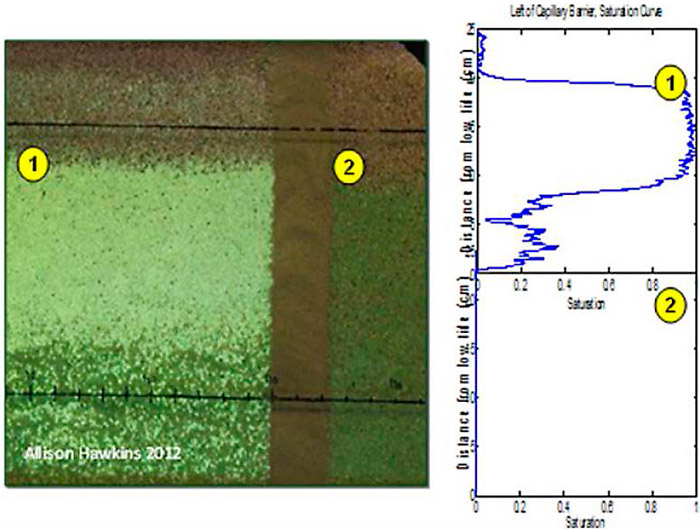
Figure S-9. 1) NAPL retention upgradient of a fine-sand capilary barrier. 2) downgradient NAPL free zone (Hawkins 2012).
Laboratory studies show that, up to a threshold NAPL thickness, capillary barriers can prevent NAPL migration while allowing water to pass (Figure S-9). The availability of large sources of sand suitable for capillary barriers can be challenging and that emplacement of fine-sand in the saturated zone, with the proper compaction and uniformity, can be difficult. Additional concerns include:
- Capillary barriers may limit cycling of aerobic water and atmospheric oxygen to the NAPL, limiting natural losses of NAPL at GSIs.
- Given a condition of constant NAPL loading and limited natural depletion, capillary barriers will fail when their capacity to retain NAPL is exceeded (i.e., LNAPL head exceeds capillary entry pressure).
Oleophilic Bio Barriers–The principle of an Oleophilic Bio Barrier is to place a composite of sorptive material at a GSI that readily conducts water and promotes aerobic degradation of the intercepted LNAPL (i.e., increase of residence time on the OBB material). Aerobic degradation is enhanced by natural cycling of aerobic surface water (e.g., tidal-driven water level changes and resultant changes in pore gas oxygen content) and/or atmospheric oxygen through the OBB. Furthermore, OBBs include an upper structural cover (i.e., rock gabions) to control erosion. Potential mechanisms for erosion (wave, current, ice, boat-induced wash) and armor requirements should be evaluated. Collectively, OBBs can address sheen releases via seeps, ebullition, and/or erosion. Sand tank images of the geocomposite are presented in Figure S-10 and Figure S-11. Figure S-12 presents an OBB with a structural cover to control erosion.
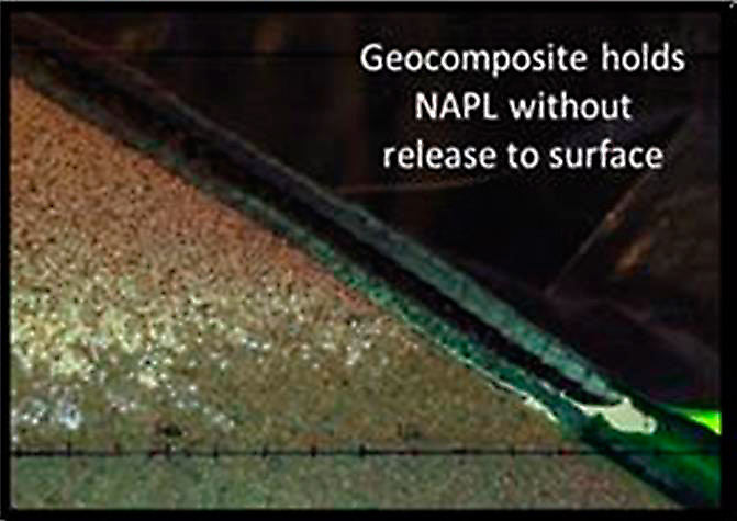
Figure S-10. Oleophilic geocomposite set at the GSI shown retaining NAPL that has migrated in a left to right direction. Surface water is dyed bright green for easy identification. Note: Photo is taken under ultraviolet light which results in fluorescence of the NAPL in the granular media on the left side of the image (Sale and Lyverse 2014).
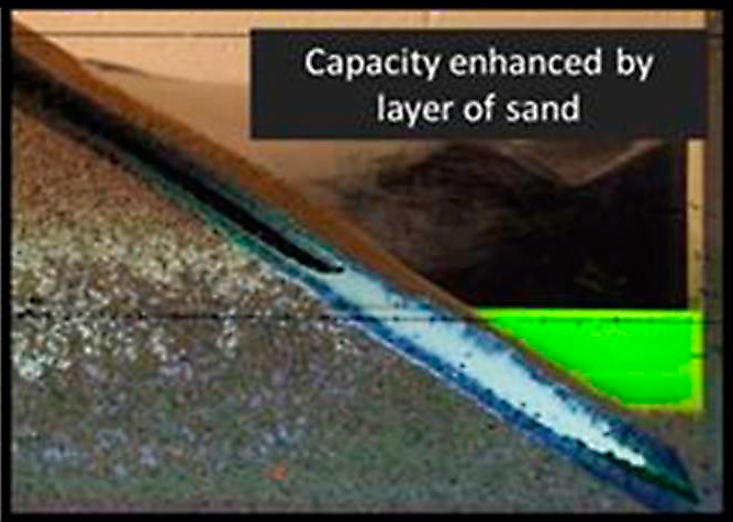
Figure S-11. Oleophilic geocomposite at NAPL-impacted GSI overlain with a sand layer to enhance the holding capacity of the barrier. Photographed under the same conditions as Figure 10 (Sale and Lyverse 2014).
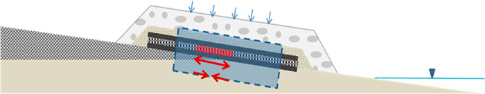
Figure S-12. Oleophilic Biobarrier including geocomposite (in black) and structural cover. Dashed grey area is an aerobic NAPL attenuation zone. Red arrows indicate lateral spreading and distribution of NAPL once it reaches the geocomposite (Sale and Lyverse 2014).
The fundamental difference between sheet pile, capillary, and organoclay barriers is that OBBs are reactive barriers. Like organoclay barriers, OBBs can last for extended periods, as long as the loading is less than their assimilative capacity. An additional concern with OBBs is fouling of the interior of the OBB with sediments. Information regarding a field application of an OBB is presented in (Biondolillo, Chalfant, and Vogel 2017) and (Chalfant 2015).

